What Are the Top 10 Mold Design Tips for Injection Molding? This question reaches beyond cavity shape and steel selection. A reliable mold must guide plastic smoothly, release the part cleanly, and remove heat without creating hidden defects. Small decisions matter. A misplaced gate can leave a visible witness mark. Weak venting can trap gas near a sharp rib. Uneven cooling can bend a flat housing after ejection.
John P. Bozzelli, an injection molding specialist and founder of Injection Molding Solutions, has stated, “The mold is the heart of the injection molding process.” That observation gives this guide its practical direction. Mold design for injection molding affects cycle time, appearance, dimensional stability, maintenance, and production cost. It also influences how consistently operators can run the machine.
The ten tips will examine draft angles, wall thickness, parting lines, gates, runners, vents, cooling channels, ejectors, mold materials, and design-for-manufacturing reviews. Each topic connects directly to the shop floor. A vent may look insignificant on a drawing. It can prevent burning and incomplete filling. A cooling channel may seem adequate. Steel temperature readings may prove otherwise.
No mold is perfect. Trade-offs remain. A faster cycle may increase warpage. More ejectors may reduce stress but complicate maintenance. Designers should question assumptions instead of copying familiar layouts. That reflective step is often overlooked. Good engineering is not merely attractive geometry; it is repeatable performance under real production pressure.
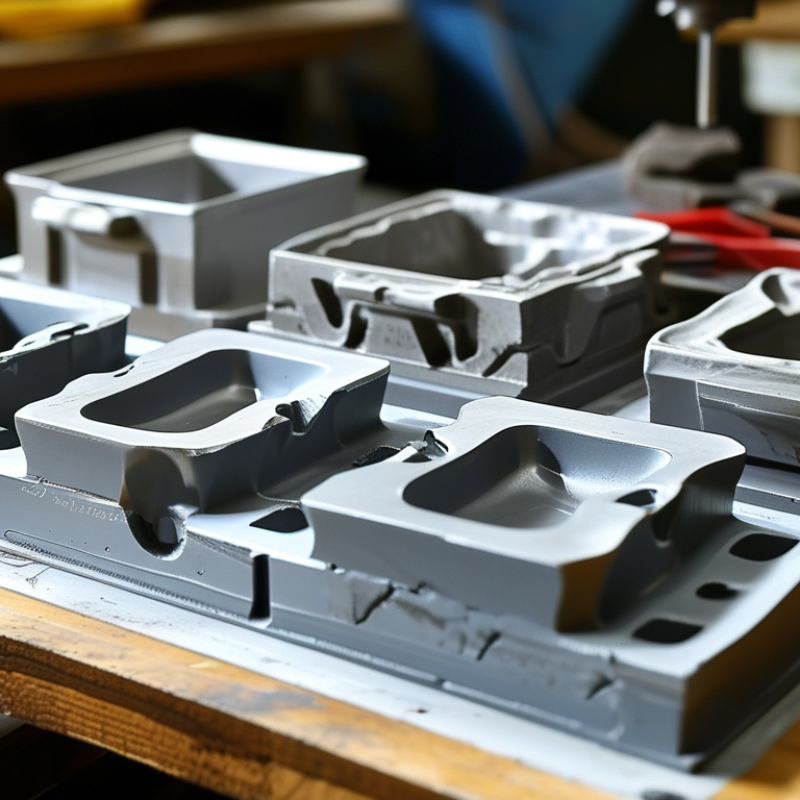
Reliable mold design starts with the part, not the machine. Review material shrinkage, function, appearance, and likely manufacturing volume before drawing the mold. Keep wall thickness as uniform as possible to reduce sink marks and warpage. Add draft angles to vertical surfaces, especially around deep cavities. Use generous radii at corners because sharp edges concentrate stress and restrict material flow. Position ribs and bosses carefully, keeping them thinner than nearby walls. Small details matter.
Define the parting line early, and place it where flash can be removed easily. Gate location affects filling, weld lines, and surface appearance. Design runners for smooth, balanced flow instead of simply making them large. Add vents near the final fill areas; trapped air can burn the plastic or create short shots. Cooling channels should follow the cavity shape and stay close enough for stable heat removal. Ejector pins must support the part without leaving unacceptable marks.
In production reviews, I have seen beautiful designs fail because ejection was considered too late. A perfect first layout is rare. Check undercuts, slider movement, mold opening space, and maintenance access during design reviews. Prototype testing can reveal unexpected distortion before hardened tooling is built. Simulation helps, but it does not replace practical judgment. I still revisit gate placement after the first trial, especially when cosmetic surfaces or thin sections behave differently than predicted.
Material selection starts with the part’s real working conditions. Identify load, temperature, chemicals, impact, appearance, and expected service life. A kitchen hinge needs different properties than a medical housing. Specify these requirements before choosing resin.
Material data sheets are useful, but they are not complete design instructions. Check tensile strength, shrinkage, moisture sensitivity, and processing temperature. Glass-filled materials can improve stiffness, yet they may increase tool wear and create directional shrinkage. A 2024 market analysis by Grand View Research estimated the global injection-molded plastics market at approximately $284 billion in 2023. That scale reflects demand, not automatic design quality. Small specification errors still cause large production losses.
Define wall thickness, draft angles, ribs, bosses, tolerances, and surface finish early. Keep walls as uniform as practical. Thick sections often create sink marks, voids, or long cooling cycles.
ASTM and ISO material standards can support reliable comparisons, but actual molding trials remain important. I have seen a theoretically strong resin fail because moisture was ignored. It happens. The U.S. Environmental Protection Agency reported 35.7 million U.S. tons of plastic containers and packaging in municipal waste in 2018, with only 8.7% recycled. Designing clear material identification and simpler part construction can improve future recovery. A perfect material choice is rare. Recheck it against production energy, recycled content, and end-use performance.
Injection molding quality often begins with disciplined geometry, not expensive machinery. Keep wall thickness as uniform as possible to reduce sink marks, warpage, and uneven cooling. Many engineering guides place common thermoplastic walls near 1.5–3.0 mm, but material choice and part size still matter. Thick areas cool slowly. They can pull nearby surfaces inward. A 2024 market report from Grand View Research estimated the global injection molding market at more than $260 billion in 2023, showing why small design errors can create expensive production waste.
Draft angles help parts release without scuffing or excessive ejection force. A practical starting point is about 1 degree per 25 mm of cavity depth, with more draft for textured surfaces. Ribs should strengthen flat walls without creating heavy sections. Keeping rib thickness near 40–60% of the adjoining wall often limits sink marks. Bosses need similar restraint. Use support ribs, generous fillets, and a hollow core rather than a solid column. These details improve filling and reduce stress concentration. Small radii are risky.
From hands-on mold reviews, I have seen a beautiful CAD model fail because one boss blocked a cooling channel. That mistake was avoidable. SPI economic data reports that the U.S. plastics industry supports over 1.6 million jobs, yet design reviews still miss basic cooling constraints. Engineers should check draft, wall transitions, ribs, bosses, and ejection access together. I sometimes overdesign ribs before validating flow; simulation and prototype feedback remain necessary.
Key starting guidelines for wall thickness, draft, ribs, bosses, fillets, gussets, and ejection features. Values are commonly used design references and should be validated against the resin, part geometry, tooling steel, surface texture, and processing conditions.
The chart presents typical starting values; the units are shown in the tooltips because the guidelines use millimeters, degrees, and percentages.
Gate location controls filling, packing, and visible part quality. Place the gate near thicker sections when possible. This reduces hesitation and limits sink marks. Keep it balanced. A gate that is too small may cause shear heating and premature freezing. A gate that is too large can leave difficult vestige marks. I usually review the gate after checking material flow, part appearance, and ejection access.
Runner design should deliver equal pressure to every cavity. Use smooth transitions and avoid sharp corners that trap material. Cold slugs need dedicated wells, especially near direction changes. Venting deserves the same attention as filling. Put vents at weld lines, last-fill areas, and deep ribs. Shallow vents are safer than oversized ones. Dirty vents can imitate poor processing. Clean them during trials and record the result.
Cooling channels should follow the cavity surface with consistent spacing. Keep extra attention near bosses, thick walls, and corners. Uneven cooling often causes warpage that processing adjustments cannot fully remove. Baffles and bubblers help reach narrow regions, but they can restrict flow if poorly sized. Measure inlet and outlet temperatures. Do not guess. I have seen a technically elegant layout fail because one blocked channel went unnoticed. Mold trials, pressure studies, and cooling-time records make the design more reliable. Leave room for maintenance, because real molds rarely stay perfect.
Ejection planning begins before the first steel cut. Set clear draft angles, balanced ejector layouts, and safe release zones around ribs and bosses. A practical rule is to monitor ejection force during trials, not only part appearance. Excessive force often signals shrinkage, poor draft, or uneven cooling. I have seen attractive samples hide these problems until production speeds increase.
Mold validation should connect design intent with measurable evidence. Check dimensions at different cycle times, resin temperatures, and cooling conditions. Record cavity pressure, cycle time, warpage, flash, and ejection marks. Use capability studies after the process stabilizes, rather than trusting one successful shot. The 2023 Plastics Industry Association Size and Impact Report valued U.S. plastics shipments at about $548 billion, showing the scale behind consistent process control. Small variations can become expensive quickly.
Maintenance must be planned around evidence. Inspect vents, leader pins, ejector components, cooling channels, and parting surfaces at defined intervals. The U.S. Department of Energy’s Operations & Maintenance Best Practices Guide reports that predictive maintenance can reduce costs by 8–12% versus preventive maintenance and 30–40% versus reactive maintenance. That advantage depends on accurate records, though. A maintenance calendar alone is not enough. Missed details matter. Photograph wear patterns, record lubricant use, and compare cycle data after every intervention. A perfect checklist still fails when operators cannot update it during a busy shift.
| No. | Design Tip | Primary Design Focus | Recommended Practice | Validation Check | Suggested Review | Priority |
|---|---|---|---|---|---|---|
| 1 | Plan the Parting Line Early | Part separation and cosmetic appearance | Place the parting line on a non-critical surface where possible. Confirm shut-off angles, wall transitions, and flash-sensitive edges before tool construction. | Inspect the first molded parts for flash, mismatch, witness marks, and unintended cosmetic defects. | At design review | High |
| 2 | Use Adequate Draft Angles | Part release and surface protection | Provide draft on molded walls, ribs, bosses, and textured surfaces. A common starting point is about 1 degree per side for smooth surfaces, with more draft often needed for deep texture. | Check ejection force, scuffing, drag marks, and dimensional change after repeated cycles. | Before mold release | High |
| 3 | Design Balanced Wall Thickness | Filling, cooling, and shrinkage control | Keep wall sections as uniform as practical. Use ribs, coring, or gradual transitions instead of abrupt changes that can increase sink marks, warpage, or residual stress. | Compare fill pattern, cooling time, part weight, sink marks, and warpage against the approved design. | During mold validation | High |
| 4 | Size the Runner and Gate System Properly | Melt delivery and packing balance | Select gate locations and runner dimensions to support balanced filling, controlled shear, suitable packing, and acceptable gate vestige for the material and part geometry. | Review short shots, pressure requirements, weld lines, gate freeze behavior, and cavity-to-cavity consistency. | First trial and setup | High |
| 5 | Optimize Cooling Channels | Cycle time and dimensional stability | Position cooling channels consistently around critical areas, avoid excessive spacing, and use separate temperature-control circuits where heat loads differ significantly. | Measure inlet and outlet temperatures, flow rate, cycle time, part temperature, and warpage at steady state. | Every validation run | High |
| 6 | Design Ejection for Even Load Distribution | Reliable release without deformation | Distribute ejector pins or sleeves near ribs, bosses, and high-retention areas. Support the part adequately and avoid concentrated forces on thin walls or cosmetic surfaces. | Check sticking, ejector marks, part distortion, pin deflection, and release force over multiple cycles. | Before production approval | High |
| 7 | Provide Effective Venting | Air evacuation and burn prevention | Place vents near the end of fill and at weld-line or gas-trap locations. Vent depth must suit the molding material and should allow air to escape without causing flash. | Inspect for burns, short shots, hesitation, dieseling, weld-line weakness, and flash around vent locations. | At first-shot review | High |
| 8 | Validate the Mold Systemically | Process capability and repeatability | Use documented trials to establish filling, packing, cooling, and ejection settings. Record mold temperature, melt temperature, injection pressure, cycle time, and part measurements. | Run consecutive cycles at steady state and verify critical dimensions, appearance, part weight, and process repeatability. | Before release to production | High |
| 9 | Use Replaceable Wear Components | Repairability and service life | Use replaceable inserts, wear plates, shut-off components, gates, and high-wear slides in areas exposed to abrasion, corrosion, or repeated impact. | Confirm component fit, shut-off condition, alignment, surface finish, and ease of replacement during planned maintenance. | During tool audits | Medium |
| 10 | Establish a Preventive Maintenance Plan | Long-term reliability and quality | Define cleaning, lubrication, vent inspection, water-line flushing, corrosion protection, alignment checks, and component replacement tasks based on cycle count and material conditions. | Track cycle count, cooling flow, leakage, flash, dimensional drift, surface damage, and maintenance findings in a controlled log. | Each shift, weekly, and scheduled overhaul | High |
Note: Review intervals should be adjusted according to resin abrasiveness, corrosiveness, mold complexity, production volume, cycle count, and observed wear.